Determination of major and minor elements by X-ray fluorescence spectrometry
Method Summary
The sample is made of lithium tetraborate and lithium fluoride as flux, and lithium nitrate (oxidant) and lithium bromide (demolding agent) are added at the same time. The sample is melted into a glass disc at a high temperature of 1050℃ and analyzed and measured on an X-ray fluorescence spectrometer. The measurement range of each element component is equivalent to the coverage range of the standard curve of each element component.
Instrument
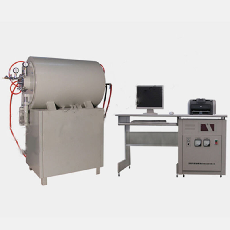
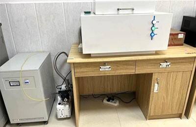
Wavelength dispersive X-ray fluorescence spectrometer, end window rhodium palladium X-ray tube, power above 3kW, and a computer system equipped with various functional analysis software such as calibration and correction.
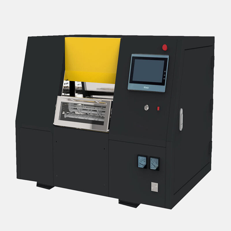
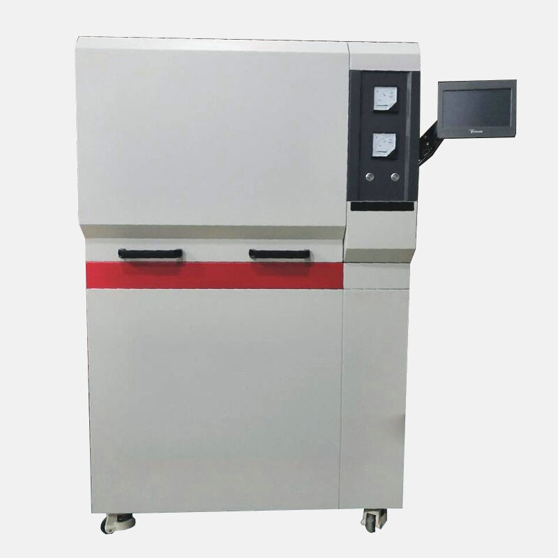
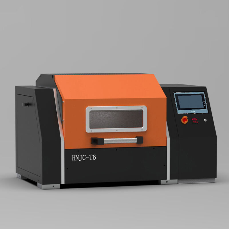
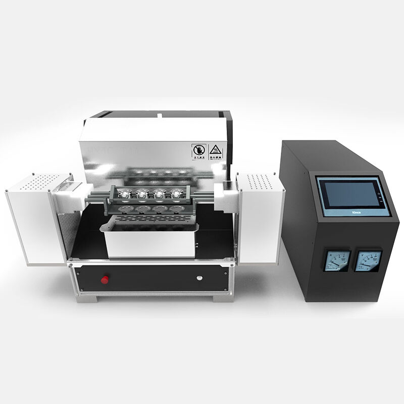
High temperature (high frequency) melting machine.
Platinum alloy crucible.
Reagents
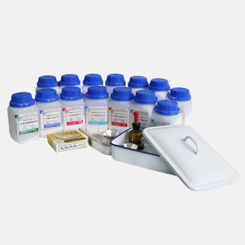
Anhydrous lithium tetraborate (special for XRF melting), pre-burned at 600℃ for 2h, stored in a desiccator for standby use.
Lithium fluoride (analytical grade).
Lithium nitrate solution ρ(LiNO3)=100mg/mL.
Lithium bromide solution ρ(LiBr)=10mg/mL.
National first-level arsenic ore standard materials GBW07277, GBW07278, GBW07163, GBW07223~GBW07226, GBW07240, etc., and select related standard materials to combine standard samples manually, so that the analysis element components include the entire content range, and there are about 17 or more standard samples with a certain content gradient.
Select 1 to 5 standard samples with appropriate content of analysis elements (components) from the standard samples as instrument drift correction samples.
Calibration curve
Weigh 0.7000g (±0.0005g) of standard sample (unknown analysis sample) that passed through a 200 mesh sieve and dried at 105℃ for 2h, 5.100g of anhydrous lithium tetraborate and 0.500g of LiF, put them into a porcelain crucible and mix them evenly, pour them into a platinum alloy crucible, add 3mL LiNO3 solution as an oxidant, 2.5mL LiBr solution as a release agent, dry them on an electric furnace, and then put them into a melting machine for melting, pre-oxidize at 700℃ for 3min, heat to 1050℃ for melting for 6min, during which the platinum alloy crucible swings and spins, and the cooling and melting process is completed. Pour out the glass piece that has been separated from the bottom of the pot after cooling, label it, and store it in a desiccator for testing.
According to the analysis requirements and the instrument, select the measurement conditions such as element analysis line, X-ray tube voltage and current, vacuum optical path and channel light bar, as shown in Table 51.2.
Table 51.2 Measurement conditions of analytical elements
Continued table
Note: ①S4 is a standard collimator.
Start the calibration standard sample measurement according to the above measurement conditions. Calculate the net intensity of the analysis line of each element (103s-1).
Use the one-point method to deduct the background, and calculate the net intensity of the analysis line Ii according to the following formula:
Analysis of rock and minerals, volume 3, analysis of non-ferrous, rare, dispersed, rare earth, precious metal ores and uranium and thorium ores
Where: IP is the peak intensity of the analysis line spectrum, 103s-1; IB is the background intensity of the analysis line, 103s-1.
Substitute the standard value of each element in the calibration standard sample and the net intensity of the element analysis line into the following formula for regression calculation to obtain the calibration and correction coefficients of each element:
Analysis of Rocks and Minerals Volume 3 Analysis of Nonferrous, Rare, Dispersed, Rare Earth, Precious Metal Ores and Uranium and Thorium Ores
Where: wi is the mass fraction of the element to be measured, %; ai, bi, ci are the calibration coefficients of the element i to be measured; Ii is the net intensity of the analysis line of the element i to be measured, 103s-1; αij is the matrix correction coefficient of the coexisting element j to the analysis element i; Fj is the content (or intensity) of the coexisting element j; βik is the spectral overlap interference coefficient of the spectral overlap interference element k to the analysis element i; Fk is the content (or intensity) of the spectral overlap interference element k.
For elements such as Ni, Cu, Zn, and Pb, RhKα, c is used as the internal standard to correct the matrix effect. First calculate the intensity ratio, and then regress according to the above formula to obtain the calibration and correction coefficients of each element.
The calibration and correction coefficients obtained above are stored in the relevant analysis program of the computer for future use.
Measure the instrument drift correction sample, and store the net intensity Ii of the analytical spectrum of each element as the drift correction reference in the computer.
Analysis steps
Prepare the unknown sample according to the calibration standard preparation method, put it into the sample box, put it into the automatic sample exchanger after confirmation, start the corresponding analysis program, and measure the sample.
After the calibration curve is established, the general routine analysis no longer measures the calibration standard series. It only needs to call the stored calibration and correction coefficients at each analysis, measure the instrument drift correction sample, and calculate the drift correction coefficient. The computer automatically performs intensity measurement and correction, background subtraction, matrix effect correction, instrument drift correction, and finally prints the analysis results.
The calculation of instrument drift correction coefficient is shown in the following formula:
Analysis of rock and minerals, Part III, Analysis of non-ferrous, rare, dispersed, rare earth, precious metal ores and uranium and thorium ores
Where: αi is the instrument drift correction coefficient; I1 is the drift correction reference intensity obtained by the initial measurement of the instrument drift correction sample, 103s-1; Im is the net intensity measured by the instrument drift correction sample when analyzing the sample, 103s-1.
The correction formula for instrument drift is:
Analysis of rock and minerals, Part III, Analysis of non-ferrous, rare, dispersed, rare earth, precious metal ores and uranium and thorium ores
Where: Ii is the analytical line intensity after drift correction, 103s-1; I'i is the analytical line intensity without drift correction, 103s-1; αi is the instrument drift correction coefficient.
Notes
1) Br remaining in the sample will cause overlapping interference to Al; when the Al2O3 content is not high, the overlapping interference correction of Br on Al should be added.
2) The YKα(2) and RbKα(2) spectral lines overlap on the NiKα analysis line. When Y and Rb exist in a certain content in the sample, they will cause overlapping interference to Ni, which should be corrected by deduction. The ZnL spectral line has overlapping interference to NaKα, which should also be corrected by deduction.
3) It is best to re-verify the measurement conditions and lower limits of different instruments.
Recommended Products
Hot News
-
Advantages and Disadvantages of High Temperature Muffle Furnaces for Heat Treatment
2025-04-21
-
How to choose a muffle furnace suitable for high temperature annealing?
2025-04-15
-
What are the maintenance measures for air permeability tester?
2025-04-02
-
What is the difference between the one-key pre-oxidation alloy melting machine and the ordinary melting machine?
2025-03-25
-
Craftsmanship creates quality! Nanyang JZJ Testing Company successfully delivered 10set customized high-temperature muffle furnaces to help the high-quality development of the refractory industry
2025-03-17
-
How to open the door of a high temperature muffle furnace at high temperature
2025-03-11
-
How to control the heating temperature and time of the multi-function melting machine?
2025-03-05
-
The biggest advantage of the automatic melting machine fusion method
2025-02-25
-
Together we build a quality future - South African customers purchased 3set of T6 melting machines in batches and delivered them successfully, and efficient services help global mining upgrades
2025-02-22
-
Detailed analysis of the advantages of using high-frequency induction multifunctional fusion machine
2025-02-18

 EN
EN
 AR
AR
 BG
BG
 FR
FR
 DE
DE
 HI
HI
 IT
IT
 PL
PL
 PT
PT
 RU
RU
 ES
ES
 TL
TL
 IW
IW
 ID
ID
 UK
UK
 VI
VI
 TH
TH
 TR
TR
 FA
FA
 MS
MS
 UR
UR
 BN
BN
 KM
KM
 LO
LO
 PA
PA
 MY
MY
 KK
KK

